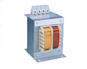
Transformers

About transformers

A transformer is an electrical device without moving parts. Its function is based on electromagnetic induction, thus it works only with alternating current. The main job for a transformer is to change voltage, lower or higher. A transformer can also be used to galvanically separate circuits which still must transfer energy. One reason for using alternating current in distributing electricity is that it is easy to change voltage levels efficiently.

About transformer characteristics

Power

The power of a transformer is reported in nominal power [S], the unit of which is VA. The nominal power is secondary voltage times secondary current. Sometimes it is advantageous to know the input power of the transformer to help determine the size of the input cable and/or fuse. This is why the data sheet also gives ΔS. Since all transformers have bigger or smaller copper, iron, and magnetization losses, ΔS is always greater than 1. When a transformer is connected to an electrical circuit there is always a surge current, thus a slow blow fuse should be connected in front of the primary winding.

Example: U=220V, S=400VA and ΔS=1.10 
        Input power = 1.10x400VA=440VA 
       Input current = 440VA / 220V = 2A

No load voltage

A transformer always has load losses (copper losses), so that secondary voltage changes according to loading. The defined secondary voltage is always reported with a defined load. So that we can calculate changes in secondary voltage, the data sheet reports Δ U. The no load voltage can be calculated by multiplying the defined voltage by ΔU. (Example: secondary voltage given as 110 V and ΔU=1.05. The no load voltage is thus: 1.05 X 110 V = 115.5 V. Secondary voltage thus varies from 110 V at normal load to 115.5 V with no load).

Efficiency

Transformer efficiency varies strongly according to their size. Generally, the larger the transformer the better the efficiency. The true efficiency of a transformer is always somewhat better than its apparent efficiency which can be obtained as the inverse of ΔS.

Deviations from type power

A transformer’s actual power can differ from the data sheet type power for several reasons. A common one is that there are several primary voltages. In this situation the primary winding needs to be designed for full power. This requires more winding space than normal, so generally we need to use more core power. 
 
Another common reason is the desire to minimize voltage loss, so that windings need to be over-sized in order to limit copper losses. Windings also need to be oversized if the ambient temperature is high. Reported type power ratings are for 50 – 60 Hz. For lower frequencies such as 16 2/3 Hz the transformer has to be larger, and for higher frequencies such as 400 Hz, smaller than the standard transformer.
 
The reported type power is for continual use. If a transformer is used cyclically, it can be made smaller. Thus it is important to report cyclical use in any order. The usage percent states what percent of usage time the transformer is loaded. Type power can be calculated like this:
 
Actual power times the square root of the cycle = type power. For example, actual power 100 VA is used for a period of 1 second every fourth second, thus the loading factor is 0.25, its square root is 0.5, thus the type power is 50 VA. In cyclical use it is to be noted the loading period needs to be significantly shorter than the transformer’s heating time. Heating time constants are generally 5-50 minutes depending on the size of the transformer. For large transformers the time constant is, however, several hours.

Auto-transformers

Full transformers have separate primary and secondary windings, but auto-transformers have only one winding which has taps for different voltages. Auto-transformers deliver more power than the type power reported on the data sheet. Type power can be calculated: the lower voltage is subtracted from the larger and the remainder is divided by the higher voltage. This result is multiplied by the desired power. It can generally be said that the smaller the voltage difference, the greater the efficiency of the auto- transformer when compared with a regular transformer. It is, however, to be noted that safety must be considered in using auto-transformers since primary and secondary windings are not isolated from each other. Auto- transformers are generally used as control and starter transformers.

3-phase vector groups

Full transformers have separate primary and secondary windings, but auto-transformers have only one winding which has taps for different voltages. Auto-transformers deliver more power than the type power reported on the data sheet. Type power can be calculated: the lower voltage is subtracted from the larger and the remainder is divided by the higher voltage. This result is multiplied by the desired power. It can generally be said that the smaller the voltage difference, the greater the efficiency of the auto- transformer when compared with a regular transformer. It is, however, to be noted that safety must be considered in using auto-transformers since primary and secondary windings are not isolated from each other. Auto- transformers are generally used as control and starter transformers.

3-PHASE VECTOR GROUPS

In 3 phase transformers, windings can be connected to star (Y), delta (D) or tapped Y (Z). The table below illustrates the most common connections.
 
Y-CONNECTION
This is the most common connection for 3 phase transformers. It is used for high and for low voltage applications. The Y-connection is obtained by one end of each coil together to form a zero (star) point to which the neutral wire can be connected. Between the outer terminals and the star point terminal appears the phase voltage, which is the main voltage divided by √3.
 
D-CONNECTION 
The D (Delta) connection is obtained by connecting the output end of one winding to the input end of the next. The applied voltage appears between each end of a winding but there is no intermediate voltage available. The D-connection is most often used at low voltages since it requires √3 times as many turns as the Y connection.
 
Z-CONNECTION
This connection can be thought of as a Y connection where each winding is split in half. The ends of one half are connected together forming a neutral point. The halves are connected in series. There is a 60° phase shift which requires 15.5% more windings than the Y connection.
 
The same connection can be used in both primary and secondary circuits (Y/Y, D/D). This is called a “clean” connection. If the circuits differ (D/Y, Y/Z) it is called a mixed connection.
 
Taking into account asymmetric loading as well as economic factors, we often recommend connection Dy11. If no recommendation is made in the order, we will deliver transformers with this connection. 3 phase transformers can be built as auto-transformers just like single phase ones. In this case connections are generally Y.

Encapsulation classes

Encapsulation serves two purposes. It protects the environment from sparks, corona, heat, voltage and moving parts which could endanger life, health or property. It also protects the device from things in the environment like moisture, dust, corrosive and other harmful agents that could damage delicate parts. According to the international IEC standard the encapsulation class is described from the letters IP followed by two identification numbers. The first number indicates the encasement’s moisture and foreign material shielding and the second its water resistance. If desired, encapsulation class can be stated with one number or the other with a large X in place of the missing number, such as IP 2X or IP X5. The following table shows the IP classes.

1st number

Description Definition

 IP 0X

 Non-protected  –

IP 1X

Protected against solid foreign objects with a diameter of 50mm and greater The object probe, a sphere 50mm diameter, shall not fully penetrate.

IP 2X

Protected against solid foreign objects with a diameter of 12.5mm and greater Protected against solid foreign objects with a diameter of 12.5mm and greater

IP 3X

Protected against solid foreign objects with a diameter of 2.5mm and greater The object probe, a sphere 2.5mm diameter, shall not penetrate at all.

IP 4X

Protected against solid foreign objects with a diameter of 1mm and greater Protected against solid foreign objects with a diameter of 1mm and greater

IP 5X

Dust-protected Ingress of dust is not totally prevented, but dust shall not penetrate in a quantity to interfere with satisfactory operation of the apparatus or to impair safety.

IP 6X

Dust-tight No ingress of dust (at a partial vacuum of 20mbar inside the enclosure).

2nd number

Description Definition

IP X0

 Non-protected  –

IP X1

Protected vertically falling water drops Vertically falling drops shall have no harmful effects.

IP X2

Protected vertically falling water drops when the enclosure is tilted up to 15º Vertically falling drops shall have no harmful effects when the enclosure is tilted at any angle up to 15º on either side of the vertical.

IP X3

Protected against spraying water Water sprayed at an angle of up to 60º on either side of the vertical shall have no harmful effects.

IP X4

Protected against splashing water Water splashed against the enclosure will enclosure from any direction shall have no harmful effects.

IP X5

Protected against water jets Water projected in jets against the enclosure will enclosure from any direction shall have no harmful effects.

IP X6

Protected against powerful water jets Water projected in powerful jets against the enclosure will enclosure from any direction shall have no harmful effects.

IP X7

Protected against the effects of temporary immersion in water Ingress of water in quantities causing harmful effects shall not be possible when the enclosure is temporarily immersed in water under standardized conditions of pressure and time.

IP X8

Protected against the effects of continuous immersion in water Ingress of water in quantities causing harmful effects shall not be possible when the enclosure is continuously immersed in water under conditions which shall be agreed between the manufacturer and the user but which is more severe than for numeral 7.

Standard type structures

The E-series transformers are normally wound to double section and chokes single section bobbin. In applications, where better coupling between primary and secondary is needed, transformers could also be wound to single section bobbin. 

 
The core is made of 0.5mm cold-rolled generator plate, type EI. Coil temperature rise is generally max 80°C and temperature class is B (130°C). If needed, we can also make transformers to meet higher temperature classes. To improve reliability, some of the insulation materials fulfil class F or H requirements. Low power models have a temperature rise of about 40°C. Products are coated by being dipped in resin, which is cured in an oven. Transformer and choke dimensions observe DIN norms and they are produced and tested according to the IEC 61558-1 standard. 
 
Products can be manufactured and tested according to other norms (i.e CSA). Encapsulated models are intended for fixed installation.  

Items to be mentioned in ordering

  • type
  • power
  • primary and secondary voltage; also secondary current as well, if there are to be taps or a separate winding connection
  • connection group, 3 phase transformers
  • possible fuse or over current protection
  • other information such as frequency, cyclic use, auto-transformer, etc.